Nylons
Nylons
Nylon is the generic term for a class of polyamides containing repeating amide groups (—CONH —.), connected by methylene units (—CH2— ) in the polymer structure. There are several types of polyamides, including the ureas, melamines, casein and other natural protein substances, which contain the amide groups, but these are arranged in a more complex polymer structure and have very different properties. The nylons are made by condensing a diamine with a dibasic acid. With the variety of diamines and dibasic acids available, many different types of nylons are possible. The most common types in commercial use today are nylon 6, nylon 66, and nylon 610. These numbers represent a convenient method of designating the nylons according to the number of carbon atoms in the segments or the starting diamine and dibasic acid from which they are made. For example, nylon 66 is made from hexamethylenediamine and adipic acid, both of which contain 6 carbon atoms. Nylon 6 uses caprolactam, a cyclic acid amide NH(CH2)5CO which contains 6 carbon atoms, as its starting material. The Nylon 610 is made from hexamethylenediamine and sebacic acid [HO-CO(CH2)8CO-OH], which contains 10 carbon atoms.
Nylon 66 is the older and more conventional type of nylon. It had its beginning in the late thirties as a synthetic fiber replacing much of the silk then used in making women's hosiery. It was not until after World War II that it was developed as a plastic. Since then it has gained in popularity because of its better heat resistance, greater strengths, and increased abrasion resistance, compared to most plastics. It is commonly used in such products as gears, zippers, fish lines, toothbrush and paintbrush bristles, plastic pipe, and tumblers.
The nylons are thermoplastics which melt at temperatures above 400°F to form a very viscous liquid, making molding of the plastic somewhat difficult. Their properties vary according to their composition and molecular weight
Nylon 6 was a German development before World War II, and was not introduced into this country until about 1952. It represents a slightly different type than nylon 66, its predecessor, as will be noted in the list of properties. Nylon 610 likewise is slightly different in properties from the other two, and consequently finds applications where the others are not suitable.
The nylons are sometimes referred to as "the mechanical plastics" because of their high strengths, all around toughness, and good resistance to heat, chemicals and electricity, thus permitting them to compete with metals in many applications. They can be readily extruded or injection molded on a mass production basis into intricate shapes and complex con tours with high precision. Because of their low coefficient of friction and good abrasion resistance the nylons are used for making gears, cams, bearings and bushings. Their excellent electrical resistance recommends them for various electrical components, such as fuse holders, insulating bushings and sockets, covering for wire and cable, coil forms, and switch components. The ever-growing number of household appliances contain nylon in their parts because of its wear resistance, quieter operation, and low maintenance, such as gears in mixing machines, rollers and slides for kitchen cabinet doors and drawers, washing-machine parts, and refrigerator shelf rollers.
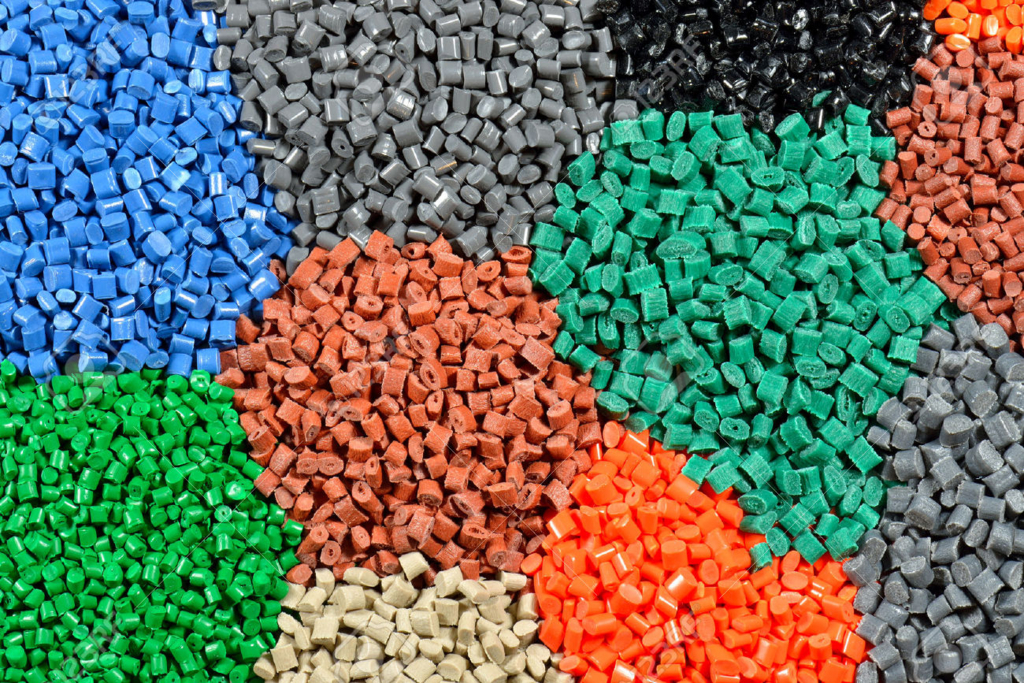
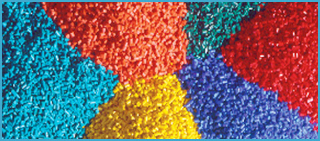
Other important properties of the nylons include good chemical resistance to most solvents and chemicals, with the exception of strong solutions of certain mineral acids, phenolic compounds, and strong oxidizers. The nylons are light in weight, with specific gravities ranging from 1.08 to 1.14. The natural color of the nylons varies from light cream to amber, but they can be had in a range of colors by the use of pigments and special dyes. They are not attacked by fungi, insects or rodents, and can be easily steri lized at steam temperatures.
In summary, the nylons are noted for:
- (1) Good mechanical properties over a wide range of temperature.
- (2) Extreme toughness, even in thin sections.
- (3) High strength-to-weight ratio.
- (4) Dimensional stability at elevated temperatures.
- (5) Excellent abrasion resistance and low coefficient of friction.
- (6) Resistant to solvents, greases, oils, alkalies, dilute acids, etc.
- (7) Good electrical resistance.
- (8) Heat and cold resistance from -100° to 250°F.
- (9) Low permeability to gases and vapors.
- (10) Slow burning and self-extinguishing.
by topworks plastic mold,a plastic cap mould maker:http://www.myplasticmold.com/cap-and-closure-mould
plastic material advantages and process
Advantages
Plastics are light in weight, but for their weight, they are prodigiously
strong. They can be changed into end products by relatively simple means,
and they have a good appearance and a good feel. The advantages in the
use of plastics as compared to other materials include:
- a wide range of color possibilities,
- adaptability to mass production methods,
- good physical properties and excellent chemical resistance.
- the over-all cost often is lower.
This last advantage is dependent on the process used to
produce the final product.
Processes
The various processes for changing the raw materials (the resins and
molding powders) into the finished items are described in Chapter 7. The
most common of these are injection molding, compression molding and
extrusion.
While there are many plastics in commercial use today the number is
still growing. The vinyls, for instance, include polyvinyl chloride-acetate, polyvinylidene chloride, and polyvinyl butyral,
to name but three forms. The most common form, polyvinyl chloride, is
what is usually referred to by the term vinyl.
Nomenclature
Because many of the names for plastics are complicated, and also because
they sometimes differ with different users, the following simplified forms
are used frequently .
ABS : acrylonitrile-butadiene-styrene
Acrylic: methyl methacrylate or acrylate ester
Acetate: cellulose acetate
Butyrate: cellulose acetate butyrate
Nitrate: cellulose nitrate or nitrocellulose or pyroxylin
Melamine: melamine-formaldehyde (sometimes called melamine resins)
Phenolic: phenol-formaldehyde
Urea : urea-formaldehyde
Fluorocarbons : polychlorotrifluoroethylene and polytetrafluoroethylene
Other terms which should be more fully understood at this point are
theromsetting and thermoplastic.
Thermosetting is an adjective applied to plastics that solidify or set on
heating and cannot be remelted. The thermosetting property usually is
associated with a cross-linking reaction which forms a three-dimensional
network of polymer molecules. Typical of the thermosetting materials
are the phenolics and the ureas. In general, thermoset materials cannot be
reshaped once they have been fully cured.
Thermoplastic is an adjective applied to plastics that may be softened
by heat and which upon cooling regain their solid state, even if the process
is repeated. Typical of this group are polystyrenes, acrylics and vinyls.
In view of the importance of terms to any approach to plastics.
by Steven ,a PET preform mould supplier:
http://www.myplasticmold.com/pet-mold
injection molding machine and injection side
injection molding machines
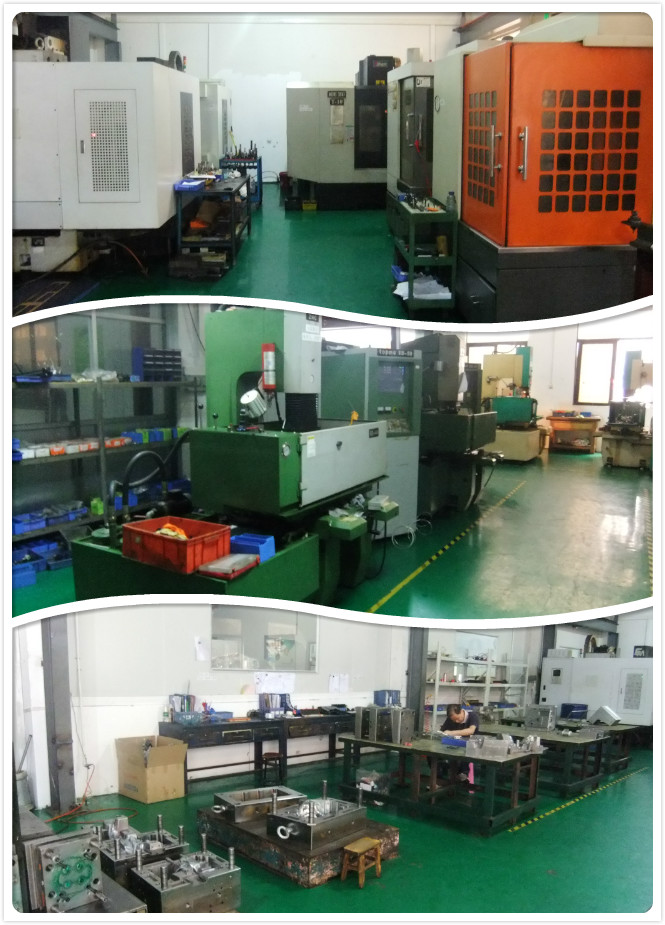
Most injection molding machines use a single electric motor to drive the hydraulic system for the entire machine. One inherent advantage of the molding cycle is that the power requirement for the hydraulic system is smoothed out because the various phases occur in sequence,As a result, a 200-ton (182-tonne) machine uses only one 40-HP (30-kw) motor; a 500-ton machine about 75 HP, and a 1000-ton machine only about 150 HP. (An additional 70-100 or more kilowatts of heater capacity must be accomodated for the 1000 ton machine.) Hydraulic system design for energy conservation is the subject of much current attention by machine builders and overall energy costs should be considered carefully by the molder.
Most hydraulic systems use fixed displacement pumps, and electrohydraulic servovalves for flow control to obtain stepless speed variation of hydraulic motors and cylinders. Hydraulic motors are efficient providers of high torque at low speeds and can be directly connected to the extrusion screw without extra mechanical transmission components. In medium and large machines, hydraulic accumulators are used to provide higher injection capacity. Redesign of circuits using cartridge valves connected {hrough manifolds instead of freestanding valves connected by pipe or hose has been hampered by high costs. These fast, compact circuits have been compared to digital electronic circuits, and the term digital or integrated hydraulics is used to describe them.
Desktop Injection Molding Machine
Injection Side
As in extrusion, general practice for screw selection with a resin that is new to a particular molder is to obtain a recommendation from the resin supplier. If a new screw has to be ordered, then rheological data on the resin should be provided so that the screw manufacturer can apply a computer program for optimum screw design. The L/D ratios for injection molding range from 16:1 to 30:1, and is most commonly about 20:1. Compression ratios range from 2:1 to 3:1. Screw and barrel designs are very similar to those described in Chapter 8 for extruders, but there is less concern with melt stability and maximum throughput than there is in profile or sheet extrusion applications. For this reason, so-called general purpose screws are often used. The length of these screws is divided as follows: about 60% for the feed section, 2 0% for transition, and 2 0% for metering. The feed depth is typically 0.20 D and the metering depth about 0.08 D, where D is the screw outside diameter.
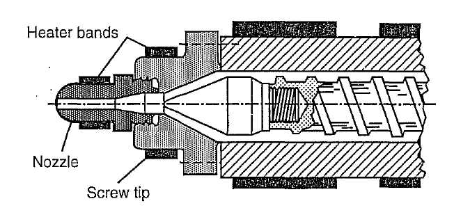
The action of the screw as a plunger during plastic injection could permit melt to leak back into the barrel and decrease efficiency. However, for relatively viscous and beat-sensitive materials, such as PVC, a plain tapered, screw-in tip is adequate (Fig. 9.8). Rapid forward motion of the screw does not permit excessive back flow. For less viscous plastics, nonreturn valves are often recommended. The free flow, sliding ring type is popular (Fig. 9.7). In sliding-ring, nonreturn valves, when the screw is rotating, plastic melt pressure forces the ring forward so that melt can flow freely. During injection, the ring slides back and seals against a lapped seat on the valve body. The small amount of material trapped in front of the ring during injection must be flushed out during the next plasticizing phase. 9.3 Machine Construction Details 281 Figure 9.8 A plain, screw-in tip for heat-sensitive plastics. This is also called a smear tip to describe its self-cleaning function. A short, open-bore nozzle for medium to high-viscosity melts (provided with a separate heating band) is shown screwed into the end of the barrel. The free flow area of the valve should be at least 80% of the flow area in the metering section of the screw.
Ball check valves are favored by some molders for ease of maintenance and low cost. Care should be taken that the valve does not introduce excessive shear heating and material degradation. A measure of the effectiveness of a nonreturn valve is the statistical distribution of part weights. If there is a wide distribution, it may indicate a leaking valve. A good distribution should have a standard deviation in part weight of the order of 0 .1%.
The nozzle is an adapter, fastened to the barrel, that provides a mechanical and thermal connection between the hot barrel and the much cooler mold. Since melt flows through the nozzle at a very high velocity during injection, the nozzle should offer minimum pressure loss consistent with prevention of excess drool prior to the injection phase. It is always preferable to use a plain open-bore nozzle rather than a more complex shutoff valve type. A short open-bore nozzle with a minimum orifice of 5 mm is a common design . A heater band and thermocouple are provided. The spherical seat on the nozzle, about 15 mm in radius, is designed to seal against the sprue bushing. The sprue bushing opening is slightly liarger than the nozzle orifice to ensure that the sprue can be pulled even if the nozzle and sprue are slightly misaligned.
Figure 1 shows a positioning or pull-in cylinder on the injection carriage. The carriage is pulled back during purging and to obtain access to clean the extruder and replace the nozzle and screw tip. It is also used to provide a sprue break feature, as previously explained. The stationary half of the mold, attached to the die head (stationary platen), is clamped against the nozzle by this cylinder.
